11/28/10

Erecting wall frames


  • The pre-nailed frames were delivered; each frame was numbered to a corresponding number on the pre-nail plan sheet so that we knew were to position the frames. The pre-nail plan sheet also gave us the dimensions of the whole house and all the individual walls and windows. From here sheet we were able to make a plan as to how we were going to erect the walls.
  • Firstly we started by erecting the two rear corner walls 1 & 2, then holding them flush to each other with clamps we could temporarily fastening them to each other with 2/100× 3.75mm nails and temporarily bracing them with 3.4m long angle braces at a approximate 45º angle down to the floor to hold them up, we than fastened them temporarily with 2/100 3.75mm galvanised nails at both ends of the walls making sure that the ends of the walls were flush with the BL and that they were square to each other by using Pythagoras.
  • From there we than straightened the bottom plates of the walls fastening them temporarily with 2/100 × 3.75mm galvanised nails at 600mm centres.
  • We then made sure that the walls were plumb at both ends of the walls, fixing them in place with 3.4m long angle braces at an approximate 45º angle to the floor. To keep the walls plumb and square we fixed the angle braces temporarily, for the walls without angle braces on them we used temporarily angle braces made from 25 × 140 timber making sure that the brace wouldn't get in the way of joining walls.
  • Once we had the bottom plate straight and the ends of the walls plumb we could than straighten the top plate holding them in position with 3.4m long angle braces at an approximate 45º angle to the floor.

    • To get wall 3 in position and all the other external walls we used the same method as we used to get walls 1 & 2 into position checking for squarnis and plumpness as we went.
    • To get internal walls in position we had to go to the pre-nail plans and check the dimensions, wall 4 was 3300mm from the inside of wall 1 to the inside of wall 4 so we than made sure that the measurement along wall 6 and wall 3
      was 3300mm, making wall 4 parallel to wall 1, and making sure that wall 4 was square to wall 3. We could then straighten and plumb wall 4 and fasten it in place.

    • We continued this process making sure that all the walls were square, plumb and straight and only temporarily fixing as we went and that all the external walls were flush with the BL and all the rooms were to the dimensions as per the plan.

  • Once we had all the walls up and standing, square, plumb, straight and flush with the building line we were than able to start fixing permanently
  • We started on the external walls re-checking to see if they were flush with the BL, and square then fixing the bottom plate to the floor @ 400 mm centres (were the joist are) along the length of the building and @ 600mm centres along the width of the building (along the laminated boundary joist) and also at door openings with 2/100×3.75mm galvanised nails.
  • We then fastened the external walls to each other making sure they were plumb and flush to each other by clamping them together and then fastening them @ 600mm centres with 2/100×3.75mm galvanised nails and a 6kN gang-plates on the top from top plate to top plate.
  • Once we had all the external walls flush to each other and the BL, square, plumb and straight we could then start permanently fixing the internal walls, starting from the bottom plate making sure they were straight and square in the room and then fixing the walls to each other making sure they were plumb. The fixing requirements for the internal walls were the same as for the external walls except for were internal walls joined internal walls we used 3kN gang-plates for top plate to top plate.

     
  • Once we had all the walls square, plumb, straight and flush to each other we could then start on putting up the double top plates, which consisted of 140 × 35mm H2.1 timber.
  • On the external walls we made the double top plate flush with the top plate to the outside, these were continuous members that were nailed @ 600mm centres with 2/100 3.75mm galvanised nails.
  • On the internal walls we made sure that the double top plate overhang 25mm on both sides of the top plate, the double top plates for the internal walls running vertically were continuous members and the double top plates for the internal walls running horizontal were cut to 400mm (450min) lengths and spaced 75mm apart to allow for the ceiling battens. The continuous members were nailed @ 600mm centres with 2/100 3.75mm bright nails and the 400mm were nailed with 2/100 3.75mm bright nails at each end
  • Once we had all the walls square, plumb, straight and flush to each other and all the top plates up we could start putting in all the vertical and horizontal bracing


     What was the process involved in straightening the exterior corner, top and bottom plates
    To straighten and plumb all the walls you firstly need to straighten the bottom plate, you than get the corners / ends of walls all plum and then you can straighten the top plate.
    • Straightening the bottom plate
  1. To straighten the bottom plate you need to firstly securely fasten the bottom plate at both ends of the wall with 2/100mm galvanized nails.
  2. You than need to run a string line along the full length of the bottom plate, with a doggie block at each end between the bottom plate and string.
  3. You than go along with a doggie block and find where the bottom plate is furtherest out or closest to the string line and move the bottom plate to where it is the same distance from the string line as the doggie block and fasten temporarily.
  4. You than go along checking at 600 centers getting the bottom plat a doggie blocks distance in from the string line, than fasten the bottom plate to the floor with 2/100mm galvanized nails leaving the head of the nail out in case you have to change it later.
  • Making exterior corners plumb

     
  • To straighten (plumb) exterior walls you need to get a straight edge that runs from the top plate to the bottom plate, making sure that the straight edge is on edge and flush on both top and bottom plate.
  • You then get your level onto the straight edge and check if it is plumb and if it is plumb you can than brace it.
  • If it is not plumb you than need to adjust the top plate until it is plumb than brace it by securely fasten a brace at a 45° angle from the top plate to the floor.
  • It is always a good idea to check if the wall is still plum after fastening the brace


    .
  • Straightening the top plate
  1. To straighten the top plate you need to firstly securely fasten the top plate at both ends with braces running from the top plate to the floor at a 45° angle
  2. You than need to run a string line along the full length of the top plate with a doggie block at each end between the top plate and string.
  3. You than go along to where the top plate is furtherist out from the string line, than move the top plate so that the string line is the same distance out from the top plate as the doggie blocks at the ends, than securely fasten the top plate with a brace running from the top plate to the floor at a 45° angle, and recheck.
  4. You than repeat step 3 until the string line is parallel to the top plate the distance of a doggie block.
    How do you make sure the rooms are square within the house?
  • By using the 3-4-5 or a² + b² = c² method on two walls you can get them square to each other.
  • From there you can get the other two walls square by making sure they are parallel to the first two walls.
  • To do this you need to measure out from where the two squared walls meet to the parallel wall, and then making sure that the measurement at the other end of those two parallel walls are the same.

DAMIAN WAIPOURI: Pre-Nail Wall Plan

DAMIAN WAIPOURI: Pre-Nail Wall Plan: "Wall Frame Plan Describe the information that that tells you how to position the frames •Each pre-nailed frame has a number on the top plat..."

11/17/10

Erecting The Roof

Pre-Nail Wall Plan

Wall Frame Plan

Describe the information that that tells you how to position the frames
•Each pre-nailed frame has a number on the top plate that corresponds to a number on the pre-nail wall plan; each frame also has a number at junction studs showing which wall is to be butted there.
What other information does it have about the timber framing?
•The Pre-nail plan has all the dimensions for the walls and the dimensions of all the windows and doors.
•The Pre-nail plan has a length of a section of wall to where an angle brace / ‘T’ section brace is to cover.
•The Pre-nail plan has all the treatments for the timber that the walls are made off, (EXT. KD H3.1 BP, H1.2 RST etc.)
Why is it supplied to builders when erecting the frames?
•It is supplied to the builder so as that they know where each individual wall goes.
•It is supplied to the builder to state that no alterations are to be made.
•It is supplied to the builder so that they know the dimensions of the walls and the rooms.
What is the ‘Disclaimer’ and what is it for
•The disclaimer state what the company’s obligations are and what they are and aren’t responsible for.
•The disclaimer state what your obligations are and what you are and aren’t responsible for.
•The disclaimer states that no alterations are to take place until the manufacturing plant has been contacted and order number issued, no claims will be recognized without the order number.
•The disclaimer states that nogs are put in to keep studs straight and aid in lining and fixing and are not to be used as an aid for climbing, and states that any damage or injury from climbing on the nogs is not the responsibility of the supplier.

Laying Insulation And Partical Board

The particle

Setting Out Joists

The joists are

9/20/10

SETTING OUT BEARERS

Bearers consist of (in our case) two 45 × 190 H3.2 treated timber laminated together and because it is a contractual load bearing member we must use MSG8 (machine stress graded) timber.


Firstly we went along and checked our timber to see which way the canver faced than put an arrow pointing in the direction the canver faced on the side the canver was, this made it easier when putting the timber in place to have the (note:1)canver facing upwards.


Now that we had the canvers we had to start (note:2)laminating 2 lengths of 190×45 H3.2 MSG8 timber to make up bearers which were to be 190×90 H3.2 MSG8 timber. We started by laying out our lengths of 190×45 timber flat on our jack studs to making sure that the canvers were all pointing in one direction. Once we had our first lot of 190×45 timber laid out we could than go over and lay our second lot of 190×45 making sure that were the connections for the first lot were in the centre of the second lot we were putting down as once we laminate this gives sufficient length to put nails and maintain the timbers strength. Once we had all our timber laid out we could than laminate them, we done this using clamps making sure to keep the side the canver was on flush.


Once we had our laminated bearers we could than fix them to the jack studs, we done this by laying the bearers on the jack studs, on edge with the canver facing upwards. We Left about 300mm overhanging the BL which we will be cutting off at a further date.


NOTE 1: We have the canver facing upwards so as when a load is applied to that member it is than able to straighten itself out and if the canver was facing downwards when a load is added to that member the canver has a high possibility of increasing.

 
NOTE 2: When laminating use 100mm flathead galvanized nails. They should be skewed in horizontally at intervals off 6 × thinnest member in a scattered pattern.

9/7/10

SETTING UP JACK STUDS

When setting out the jack stud plate you need to pay a lot of attention to make sure these are in place horizontally, parallel to the BL. With the actual jack studs you want pay specific detail to the height and make sure they are on a horizontal level plane and also vertically level.


- STEP 1

1. The first step to setting out your jack studs is to get all your string lines in place. To do this you firstly need to transfer our building lines onto our profile bottom plates, then go back over and check all our measurements and make sure they are still the right lengths and that the string lines are square and if they aren’t just adjust them till all the measurements are bang on.

2. Once all your string lines were in place we just want to mark them onto our profiles and identify them as building lines by putting a BL next to them.


· STEP 2

1. You can now start marking up on the profiles where your bearers are to go by getting all your measurements from your plans. On side A we had cantilever joists that over hung the bearers by 300mm so therefore we had to set up a string line in 330mm from the building line.

2. On side B of the building one of the walls stepped in 600mm and ran about half the length the building so we had to set up a string line in 630mm from BL and another 30mm for the other half the length the building, we also had to set up string lines at each end 30mm in from BL.

3. We then marked these so as to know what the string lines represent, usually with the distance in from BL, and an arrow showing were the measurement goes to from the BL(e.g. B│L >30│ or │<30 B│L)
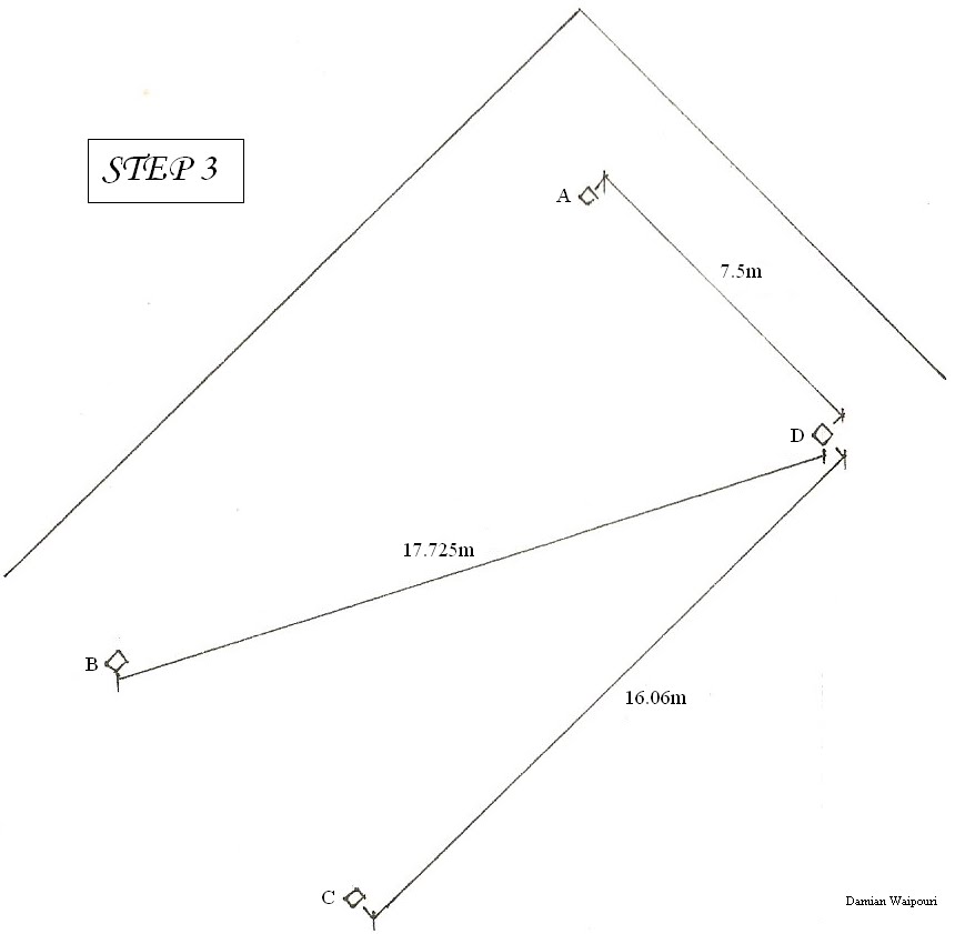

· STEP 3

1. Now that we knew where the jack stud plates needed to go we could start setting them out. We started by getting the necessary lengths that we required and laying them out in place but not fastened.

2. When it came time to fasten we started by nailing both ends in line with the string line and in some cases only one end depending on how warped the length of timber was.

3. Fastening the jack stud plates

(a) We than went along and placed spacers along each end as to keep the string line of the length of the member and keep it from being altered. We could than go along with some more spacers and line the boards up parallel to the string line at the space of the spacers and fasten them to the tarmac, starting from one end and working our way to the other end.

(b) For the timber that was to warped to use method 3(a) we lined one end up with the string line, with the canver facing the string line or so the timber was arching away from the string line. We then went along nailing it in starting from the fasten end, we than bent it in towards the string line until it lined up with the string line and at the point where it just curved away we would fasten it and so on until we got to the end.


· STEP 4

1. Now that we had our jack stud plates we could start on putting in the jack studs, because where we were going to be putting the jack studs was on an angle we had to get the length of the longest jack stud that we require and we could than cut all the jack studs that we required to that length.

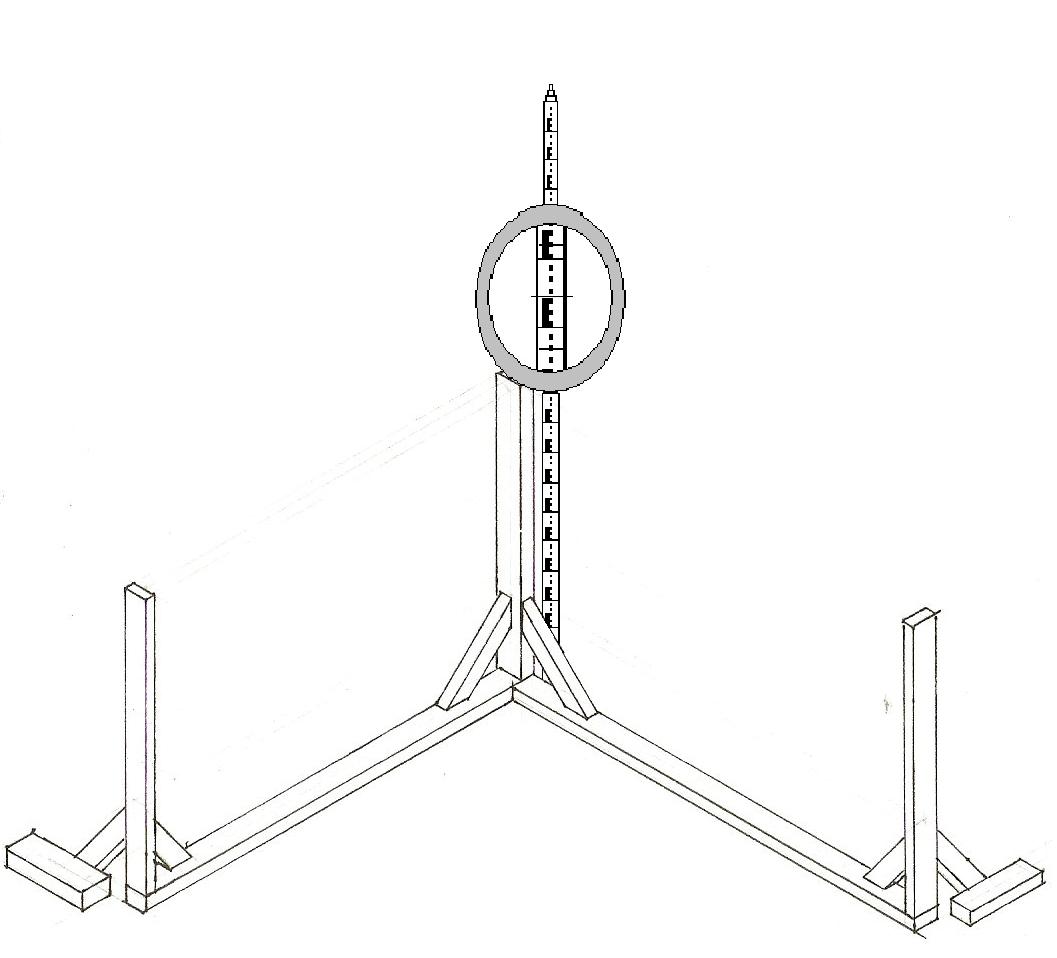
2. After positioning all the jack studs we were than able to level them all out, we done this by using the dumpy and getting the height from our jack stud level at our datum point, and using the method that we used for our FFL on our profiles (setting out profiles - step 3: 2) we were able to get the lengths of all our jack studs; measuring them up one by one.

3. Once we cut all the jack studs to length and put them back in place we than had to go back over and check them all with the dumpy to make sure, for one that we had them all in the right place / order and secondly that they were the exact length so that they were all on a horizontal level plane.

· STEP 5

1. Now that all the jack studs were in place we were than able to fasten them to the jack stud plates, We had to make sure that the studs were flush with the string line side of the plates when fastening them. We fastened the studs at ____ centres with two 100 mm galvanised nails one on each side skewed down.
2. Once we had fastened all the jack studs we than had to brace them as to keep them level in the direction of the plate. For the braces we used 90 × 45mm timber on one side and 140 × 20mm timber on the other and these were braced at 45°. We also braced the end jack studs perpindicular to the jack stud plate as to keep the end jack studs straight up.


Note 1: The building line indicates were the outer edge of the FFL will be, because boundary joists over hang the bearers by 30mm hence the extra 30mm in from the building line.

PROFILES AND DATUM POINTS

SETTING OUT PROFILES


This process takes a bit of checking and changing and double checking which is essential cause the profiles gives us our FFL (final floor level) our Jack Stud Heights which every vertical measurement are measured too at our datum point (1.), and our BL which every horizontal measurement is measured from at our profile/batter boards, 330 mils this way 30 mils that way etc,


· STEP 1


1. So firstly we started working out the minimum lengths for our batter / profile boards and leave sufficient room for our building line and also the lines for our Jack stud / Bearer lines (which were 30mm,330mm and 630mm in from our building lines) and joist lines(which were 300mm and 600mm in from our building lines).


2. Once we worked out the lengths of our batter boards / batter board plates we were able to start setting out our profiles, these were to be 1m out from our building lines.


3. Once we marked it out we were than able to start putting in our profile plates and uprights and bracing them, we had to brace each upright with at least two braces as to keep it square, with braces going perpendicular to each other.


· STEP 2


Once we set out our uprights we than had to find our datum point (1.), this point is the point to which all vertical measurements are measured from. To find our datum we had to use a dumpy and staff (2.); we went around and measured the height at the corners of each profile. The lowest measurement was our highest ground level point and therefore our datum point.


· STEP 3


1. Now that we had our datum point we were able to get our FFL which was 850mm (3.) high at the datum point, we started by putting up the profile boards at the datum point first and leveling them out.


2. Then we went back to our dumpy and got the measurement up from our datum point profiles and marked this on our staff, we were than able to find the height of the other profile boards by using the dumpy and staff, by moving the staff up or down until the line on the staff lined up with the middle line in the dumpy and made a mark at the bottom of the staff onto the corner profile uprights, this then transferred a level horizontal line from the datum point to the three other profiles.


3. We then put up the rest of the profile boards only partially nailing them in, once they were all up we were than went back over and double check the height and fasten them properly once the heights were right.


· STEP 4


1. Now that we had our FFL we were able to get our jack stud height profile boards which was 400mm below our FFL, we done this by using the same process to get our FFL profile boards up.


NOTE 1: A datum point is the point to which all measurements through the dumpy are taken, this point is always the highest point on the site. You need be particular with all your measurements at this point, as if you get it wrong here you than transfer it to the other points wrong.

NOTE 2: A dumpy and staff is used in a system for transferring a height from one point to another at a level horizontal line

NOTE 3:To get our FFL we added our bearer (190mm), Joist (190mm), particle board (20mm), jack stud plate(50mm), and jack stud(400) which gave us a FFL of 850mm and a jack stud level of 450mm at our datum point.


SETTING OUT STRING LINES

Setting out profiles! Well we started off by setting out the pegs (paint marks) to our building lines

STEP 1

We started off by setting out our two first pegs which made our main building line which was 3m out from our "side boundary" and 2.5m out from the rear "boundary" and was 16.06m long.The main building line is a fixed line (should not be altered) and therefor gives a point to work off.

STEP 2

Then we moved onto the third peg which we found by measuring 7.5m from one of the established pegs and 17.725m from the other peg where these two measurements met was the position of our third peg

STEP 3

We could than start on setting out our fourth peg, we found this by measuring 16.06m from our third peg parallel to our main building line, 7.5m perpendicular from main building line and 17.725m diagonal from the remaining peg on the main building line, all of which should have met at the same point at to which was our fourth and final peg.\

STEP 4

We than extended 2m at each end of each line to which we placed pegs and fastened string lines, this than formed our building lines. Once we had our string line up we could then go over and double check our measurements which were 16.06m and 7.5m parallels and 17.725 diagonals.


NOTE 1: You aren't always given the diagonal and therefor may have to find it your self. This is found by using the method of A squared plus B squared equals C squared, A (16.06)and B (7.5) being the two perpendicular (90*) lines and C (17.725) the diagonal. This method is used for gutting two lines square (90*) to each other.

NOTE 2: Usually when your finding your building lines the plan will have more than two "maybe" up to 4 measurements in from the boundary line to your building lines.